continuous flows in the emitter and collector are in normal operation by: The internal power base is mainly by diffusion and
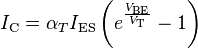
I C is the collector current. Α
T is the direct current gain in common base configuration. (From 0.98 to 0.998)
- ES
- is the reverse saturation current of base-emitter diode (in the order of 10
- -15 -12
-
 to 10 amps)
 -
 V
V
- T is the thermal voltage k
-
![J_p(Base) = \frac{q D_p p_{bo}}{W} \left[e^{\frac{V_{EB}}{V_T}}\right]](http://upload.wikimedia.org/math/9/6/f/96f699c8d9fe9e6f131c4966a5a128e2.png)
T / q
- (approximately 26 mV at room temperature ≈ 300 K). V BE
- is base-emitter voltage. W is the width of the base. The collector current is slightly less than the emitter current, because the value of αT is very close to 1.0. In the bipolar junction transistor is a small variation of the base-emitter current generates a large change in collector-emitter current. The relationship between the current collector-emitter to the base-emitter is called gain, β or hFE. A β value of 100 is typical for bipolar transistors smaller. In a typical configuration, a very weak signal current flowing through the base-emitter to control the current emitter-collector. α β is related through the following relationships:
- issuer Efficiency: Other equations are used to describe the three streams in any region of the transistor are expressed below . These equations are based on the transport model of a bipolar junction transistor.
- Where: i C is the collector current.
- i B is the base current.
- i
- E is the emitter current.
-

- F
 β is the active gain common-emitter (20 to 500)
 -

 β is the inverse common-emitter gain (0 to 20)
 I 
S 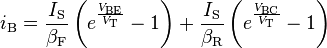 is the reverse saturation current (in the order of 10
- V T is the thermal voltage k
- T / q (approximately 26 mV at room temperature ≈ 300 K).
- V BE is the base-emitter voltage.
- V BC is the base-collector voltage.
- Posted by: Emmanuel Angel
0 comments:
Post a Comment